NOTE – The control voltage to raise / lower jacks changed in newer models. On mine, the control module supplies a ground to energize the solenoid valves. On newer models, the module supplies 12 volts to energize the solenoid valves. Make sure you test so you know if you need to supply ground or 12 volts.
I can lower the jacks individually, Wouldn’t it be great if I could also raise them individually?? READ ON.
This is a modification I’ve been thinking about since buying our Southwind two years ago; being able to raise the leveling jack(s) individually, a little or a lot.
When leveling my Southwind, it always seems like one of the jacks is down just a little bit to far, and all I’d need to do is raise that jack an inch or two and the level would be perfect.. BUT, Power Gear doesn’t let you do that. URGH… The only way to retract a jack is to press the “RETRACT ALL JACKS” button, then quickly turn the system OFF to prevent the jacks from retracting all the way, then start the leveling process over again. ..
I can lower the jacks individually, but Power Gear doesn’t have a way for me to raise the jacks individually, UNTIL NOW
HOW THE POWER GEAR SYSTEM WORKS
LOWERING JACKS
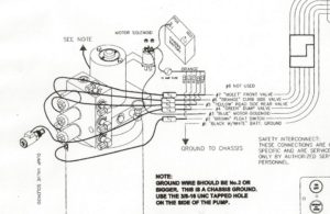 When a RAISE COACH buttons is pressed, the controller does two things:
- 12 volts is applied to the BLUE wire. This energizes the pump motor solenoid. the pump motor starts to run, and the pump applies pressure to the three jack valves.
- A ground is applied to the jack solenoid(s) whose button is being pressed. The jack valve opens, allowing fluid to flow from the pump to the jack, and the jack moves down.
When the RETRACT JACKS button is pressed.
- A ground is applied to the GREEN wire (Dump valve) This opens the dump valve. Any pressure / fluid from the three jack valves is dumped back into the reservoir tank.
- Grounds are applied to the three jack solenoids. All three jack valves open. The springs on the jacks pull the shafts up pushing fluid out of the jacks, through the open jack valves, then through the open dump valve, back into the reservoir tank.
HOW THE MODIFICATION WORKS
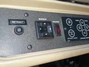
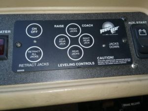
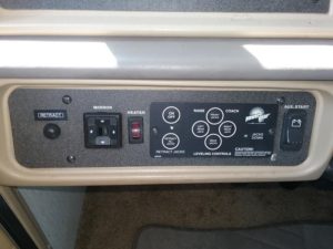
The modification allows individual jacks to be lowered or raised by any amount. To raise a jack, press and hold the new “RETRACT” button down, then on the Power Gear panel, press and hold the RAISE COACH button for the jack that you wish to raise. When the newly installed “RETRACT button is held down, it does two things:
- It disables the pump motor so the pump motor won’t run. It does this by energizing the pump disconnect relay. When this relay energizes, it opens the motor control contacts so the pump motor cannot run when one of the leg down buttons is pressed.
- It supplies a ground to the DUMP” solenoid. The DUMP solenoid energizes and opens the internal dump valve.
While pressing and holding the RETRACT button, simultaneously press one of the RAISE COACH buttons. This energizes the corresponding jack solenoid and opens the jack valve. With the jack valve and the dump valve both open, and the pump not running, the spring on the jack pulls the jack up and dumps the fluid back into the reservoir.
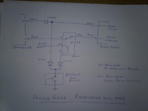
This modification took about 2 hours to do. Wire the relay, push-button and diodes as shown on the diagram.
- Momentary contact (normally open) push-button switch (EXAMPLE)
- Single pole double throw relay with wire pigtail (EXAMPLE)
- 3 each 1N4001 diodes (EXAMPLE)
Making the modification is fairly easy if you have reasonable electric skills.
- Disconnect the chassis battery
- Remove the “PUMP HARNESS CONNECTOR” from the controller. Open the harness to expose the wires about 4 inches up from the connector.
- About 4 inches up from the connector, cut the BLUE wire (motor control) and the GREEN wire (Dump valve)
- Solder the cut BLUE wires to terminals #30 and #87a (normally closed contacts) of the relay pigtail. There is no connection on relay terminal #87.
- Refer to the diagram, solder leads and diodes to the push-button switch. One end of the push button goes to a ground. I used the PCM ground terminal near the floor behind the parking brake, the other end of the switch has two diodes connected.
- Observe polarity (see photo) when installing the diodes. Solder one diode to the relay coil terminal #86 of the relay. Solder the other diode to the cut GREEN wire that goes to the dump valve. This diode isolates the push-button switch.
- Solder a third diode between the two cut GREEN wires, observe polarity. This diode isolates the controller.
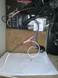
- Refer to the controller photo – Splice the other relay coil terminal #85 to the white wire indicated. This will supply 12 volts to the circuit when the IGN switch is turned on.
- Plug the controller back in and reconnect the battery.
TESTING
- Parking brake set, Engine running, and transmission in PARK. Turn the Power Gear panel ON.
- Press and hold any of the RAISE COACH buttons to extend the jack(s). i.e Front jack. The pump should start and the jack should extend. Release the button when the jack makes contact with the ground
- Press the new RETRACT button, you should hear the relay energize. The relay should de-energize when you release the button.
- Now, Press and hold the RETRACT button. Then press the RAISE COACH button you used above, i.e the front jack. The pump should NOT run and the jack should actually retract as long as you hold the RAISE COACH button on the Power Gear panel at the same time you hold the new RETRACT button down.
- IMPORTANT – When you release – always release the extend button on the power gear panel first. then release the new RETRACT button last.



Hi, question. The leveling jacks on my 1999 southwind wont retract at all. Any idea why?? Ty for any onfo.
Check the 3 amp fuses on the control panel.
In retract, all four solenoids should energize; the retract solenoid and the three down solenoids. These are locate on the valve manifold assembly which is part of the pump, valve, and tank assembly.
Awesome solution. I have a similar system (#500675, see http://techsupport.pdxrvwholesale.com/wp-content/uploads/2019/07/Power-Gear-Service-Manual-82-L0506.pdf). I came across this article cause my control panel does not light up any more: I applied 12v to the solenoids to retract the jacks “manually” since I had to leave the campsite…
Interesting that you have to supply a “ground” to the jack solenoids, in my case I have to supply 12v…
Question for you, what is the dump valve used for? It seems I can retract the jacks by just applying 12v to the 3 individual jack solenoids. Do you have a schematic that shows the hydraulic lines/valves with motor etc.?
I’m considering replacing the whole control box with my own electronics (esp32 so I can tie the jacks into to smart rv that I’m planning to build).
Yes, my system is a little older, 12 volts is supplied through a fuse to all four solenoids at the connector harness plug near the reservoir and pump. The controller then supplies the ground to complete the circuit. You can see this in the Power Gear circuit diagram thats part of the article.
On my system, I would expect yours to be similar, there is a central passage that feeds fluid to all three solenoids. Fluid to the passage is supplied by the pump. The DUMP valve allows the passage to drain back to the reservoir.
Applying power to only the three leg solenoids won’t retract. power also needs to be applied to the dump valve
To get fluid to flow from a leg, the solenoid for that leg must be open, this allows fluid to flow from the leg into the passage. Then the DUMP valve must be open to allow flow from the passage to the reservoir.
My levelling system stopped working entirely. It appears to be a fired component in the controller box and has become completely unresponsive. Replacement parts are around $700 and I’m not certain this is the (only) problem.
Do you think there is a way to bypass all of these electronics and just add switches that lower and raise the jacks using the existing hydraulics?
PS: I love your site! I have a 1999 Southwind 36T and I could ask for more. Thank you for doing this, I appreciate what you do.
Yes, its possible to energize the solenoids directly, but keep in mind this bypasses all the safeties.
What are the risks of bypassing the safeties? Aside from death and dismemberment, are these generally high risk/danger components?
I don’t use the jacks now and use RV leveling chocks to get level.
My greatest concern is that I can’t retract the jacks, and I am unable to move when I need to leave a park, because my jacks are stuck down and I can’t fix it.
Is that a real problem I need to be concerned with?
Bending jack shafts would be the biggest concern, then you can’t retract them, and the only way to move would be to physically remove the jack.
Thank you for the article. It looks like from 2002 or so and later the solenoid power is reversed, so reversing the diodes in your schematic, and reversing ground and power on the added switch should cause it to work as you describe. Looks like the wire colors stayed the same. Now, if I could just find the control box on my bus.
Systems defined here: https://lci-support-doc.s3.amazonaws.com/manuals/leveling-and-stabilization/ccd_0002309.pdf
I placed a note at the top of the article to advise that this may be different.
I have a 500210 controller and my pump stays on as soon as I turn key switch to Acc. Question, how do I test if my pump solenoid needs a ground or 12 volts to activate. One side of the solenoid has 12 volts already but I saw a comment that there is two different systems one that requires a ground and the other to raise voltage ? I’m getting 12v from wires on second lead of solenoid to controller, If I applied a ground I would get a short correct ?
I have a 1997 pace arrow vision
Look at the pump motor, there is a starter solenoid attached to it that has two large wires, one is the 12 volt feed, and the other goes to the motor. There is also a small wire that controls the solenoid. Remove this wire. Then use a voltmeter to check the power on that terminal. If you see 12 volts, then you need to supply a ground to energize the solenoid.
Good morning, I need to replace a resistor on my 500210 power gear controller. Can anybody provide me with an image or resistor value? It’s the big resistor next to the ribbon cord. Its label R29. The ribbon court is J 20.
Good morning I need to replace a resistor on my power gear 500210 controller. Can someone help out by providing me a picture or the resistor value . The resistor is located next to the ribbon cable label J 20 in the resistor value is label R29 it’s right on the corner of the board.
I have a 2002 Excursion 394S and the jacks wont come up. The controls have green pwr light and no light on for jacks down. Where is the fuse for the power gear system/? anyone know what I should check? I checked the fused in the control box under the dash on the floor in center. and the 15a inline at the big pump under the rear on passenger side . Any other ideas? I would appreciate it. Thank you in advance
If the JACKS DOWN light isn’t on, it might think the jacks are already retracted.
Will the jacks go down if you press any of the down buttons??
I have a 1999 Fleetwood Discovery with this same jack system. I replaced the motor, solenoid and bearing as the motor was dead (bearing was worn out). Jacks go down, but won’t go up. I verified continuity between the green wire at the controller and the green wire at the dump solenoid. I pulled the dump solenoid and valve and bench tested it. Solenoid is 7ohms, with 12V applied it makes a small noise like it is operating but I’m not sure how to test it further.
When I press retract, nothing happens. All Jack valves must work because the jacks went down. Any idea how I can test the output of the controller? My controller provides ground (like yours) but I can’t detect continuity between the wires at the controller and ground when the solenoids are operating, maybe due to something with my meter or a transistor in the system somewhere?
I’m stuck and not sure what to check next.
The only thing I could think of would be to manually ground the dump solenoid to energize it. At the same time manually ground the front, or the two rear solenoids to energize them. If this works, then the problem is in the controller.
Good suggestion, will give this a try and report back. If it turns out to be the controller, is that leveler control via the Waiter ECC that you posted about a while back ready for prime time? And, does it require a functioning power gear controller or is it a full replacement?
Bad news, energizing both the front Jack valves and the dump valve caused the front jacks to retract. Meaning that the problem must be my controller. The controller itself must recognize that I’m pressing the retract button because when I do, all of the other buttons stop working. And as I understand it, that is normal. But, nothing retracts.
Any chance you’re leveling controller is available for purchase?
Turns out this was an id10t error. During re-assembly, I connected the positive coil supply wire to the wrong post on the motor contactor, which meant that the coils only had positive voltage supply when the pump was being activated (jacks down). I swapped the orange supply wire from the load post to the supply post and everything is working properly.
Excellent
Bonjour
Moi c’est un peu le contraire j’ai sorti les fack du devant au complet pour faire des tests
J’ai pu les remonter mais depuis ce temps tout fonctionne sur les boutons mais ils ne sortent plus et je ne sais pas de quoi ça dépend